Summer 2005
- Part 1
Building a new exhaust system
|
The exhaust system I have
been using so far is a pair of pipes taken off the bikes which I bought
back in April 2003. I had two
pairs of pipes, and I had used two right hand side pipes on the
hovercraft - this meant they fitted side by side rather than splaying
out like a pair of legs.
I had mounted the pipes vertically from the exhaust flange up over the
front
of the duct guard to exit near the top of the duct. It had been a quick
solution - the pipes had just needed the first bend in the header pipe
tightening up a little (by cutting and welding) to make them fit into
the space available between the engine and the cockpit side.
|
The problems with this arrangement were::
1) the mounting was difficult - the front one was tied to the RHS
bracing strut and the rear one was tied to the duct guard using jubilee
clips. There was no allowance for any flexing or vibration.
2) they blocked the flow of air through the fan
3) they were pretty heavy
4) they raised the centre of gravity unnecessarily.
In the end, the poor mounting arrangment meant that at Gang Warily in
May both pipes cracked
at the first bend. I welded them up but they cracked again. I decided
that I needed to do the
job properly and replace them with something better. A lot of
TZR-powered hovercraft use custom made exhausts, which run
over the RHS deck next to the duct. I was keen to build such an exhaust
system which would solve all of the original problems.
|
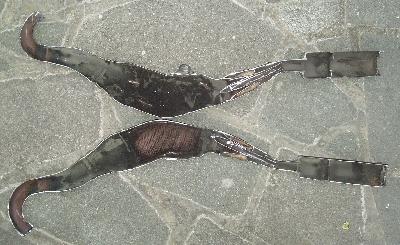
I cut one of the spare pipes
in half with a large angle grinder to have a look at the inside. It
is made from many individual pieces of steel, pressed and welded
together. The basic shell is 1.2mm thick, but in most places an extra
sheet has been pressed in, doubling the wall thickness, so the weight
is many kg per pipe. The silencer cans are welded on but the wadding
inside can be replaced by removing a screw and withdrawing a perforated
tube.
Rather than rebuild an exhaust using multiple pieces of sheet, I wanted
to try hydroforming - the
technique where two flat shaped
sheets
of steel are welded together around their edges and then
inflated under extreme pressure to form a cylinder of whatever shape is
required.
As the original pipes had welded-on silencer cans I would
also need
to either buy or make replacements cans.
|
HYDROFORMING IS POTENTIALLY VERY
DANGEROUS AND INVOLVES VERY HIGH PRESSURE
A bit about 2-stroke exhaust pipes
A 2-stroke exhaust pipe is a complicated beast. Unlike a 4-stroke
exhaust system teh 2-stroke exhaust is really part
of
the engine and not just an add-on component.
The 2-stroke exhaust uses several identifiable sections - the header
pipe, the front cone, the parallel section, the rear cone and the tail
pipe. Each of these components plays an important part, according to
the laws of physics - mainly transmission line theory. In particular,
the cones produce reflections which send pulses back to the engine to
suck out exhaust gases (a negative pressure pulse) and force the fuel
air mixture in (a positive pressure pulse). The time taken for the
pulses to travel along the exhaust pipe depends on the length of the
pipe, and the speed of sound in the hot exhaust gas. Because the pulses
travel
down the pipe at a fixed speed, the whole system is set up for a
particular engine speed - peak power at around 10,000 rpm, which is
what tuning is all about.
Testing out the ideas
One of the questions that I needed answering is how
much pressure would I need? How easy is it to weld stainless steel? My
friend Clive loaned me a high prssure hand pump which could reach
350psi. Would this be enough?
As I had a large quantity of 1.5mm thick stainless steel sheet handy, I
cut out a pair of identical shapes from this and bent the edges over a
little. At one end I welded in a length of pipe with a 1/2" BSP
thread to fit to the flexible reinforcedpipe from the pump, and at the
other I
welded in an 8mm nut to use as an air bleed off valve.Then I
welded the edges together. This was meant to be just a test piece to
try out the technique - which is why it doesn't look much like an
exhaust pipe.
I pumped up the pressure a little and bled out the air. Apparently, if
you expel all of the air then you are only compressing water. If
anything
bursts then the pressure will immediately drop, without the whole thing
exploding. The first test was too see if it held pressure. At 50psi I
noticed
that
the welded joint around the 1/2" BSP steel pipe was leaking a little so
I
drained it all down and rewelded the hole.
Then I pumped it back up and continued pumping. At 100psi I thought it
was scarey stuff! The pressure soon increased and the bleed valve
started leaking slightly around the threads - I hadn't used any PTFE
tape (didn't have any). But I kept pumping and the test piece inflated
gradually. At
330psi the pump was getting difficult and the test piece looked fully
inflated.
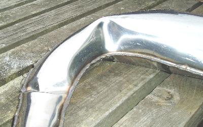
Hey this looks easy! It had inflated to a smooth shape - with just a
small kink where the edge had a bit of a poor shape The test piece
was strong enough that even when emptied of water it could easily take
my weight
standing on it,
but then again it was a
little too heavy. If the pump
could cope with 1.5mm thickness steel, I thought it should easily cope
with
thinner stuff. I bought a sheet of 0.9mm grade 304 (that's A2)
stainless from Outlooks.
OK. So the test piece showed that it was possible to produce a
stainless steel envelope and inflate it. So what I needed now was a
design for the actual exhaust dimensions.
 |
The book provides plenty of guidance and theory but it also makes
exhaust design sound complicated. The cone flair angles, cone lengths
expansion chamber widths, stinger dimensions are clearly all important
but it is always difficult to appreciate how critical each dimension
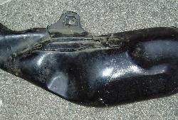
is. Looking at the original Yamaha exhausts, they are clearly a
compromise
between the theoretical shape and what can be made in practise.
In particular, a large dent designed-in to the side of the pipe
allows it to clear part of the bikes engine/frame which sticks out, so
it's obviously
not too critical in places. |
One thing worth noting is that while the dimensions are generally
important, the bends in the pipe are not. So as long as the lengths and
widths of each stage are correct then you can bend the whole thing to
make it follow whatever shape you want. Another point to consider is
that hydroforming only allows bends in one
plane, so to create a more
complicated shape the pipes need to be cut, twisted and rewelded.
This means that you can (in theory) design your entire exhaust pipe out
of two flat shapes, allowing for the fact that you are going to twist
each section as required. The cross-sectional area is dictated by the
theoretical design. But
assuming the pipe is circular then the width of the template needs to
be half of the circumference of the finished pipe. Then when it is
blown up the two sheets form a complete circumference of the required
size.
I cut out a paper pattern for the exhaust shape according to the half
circumfernce rule above and transferred this onto the stainless sheet.
When drawing the bends in the pipe you need to allow for the fact that
as
the metal inflates, the bends close up by around 10%, but this is
all a bit hit and miss. I wasn't exactly
sure
that I had the right shape, but I needed to give it a go. I cut out a
pair of exhaust shapes using an air powered nibbler (much
quieter than a portable jigsaw), welded the edges together, welded on
the inlet and outlet ports and pumped it up as before.
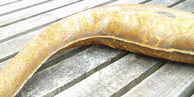
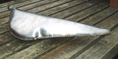
This first exhaust shape was a bit of a disappointment after the
success of the test piece. The problems were:
The wide section (expansion
chamber) inflated first, and this caused a
major kink in the metal at the end of the header.
I had allowed 3mm extra width to accomodate the welding - this wasn't
enough and the overall diameter came out too small - especially around
the header pipe section.
The edge of the pattern had been a bit wavey - this caused ripples in
the edge of the inflated pipe.
The bend radius of the pipe was to tight and kinked one side.
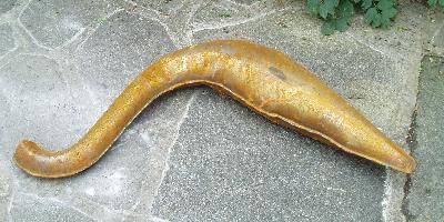
A lot of these problems seemed to come down to the fact that I was
using stainless steel which is harder and less ductile (stretchy) than
mild steel. I modified the design with:
extra width to accomodate welding
smooth straight sides to prevent ripples
greater bend radius to prevent kinking